

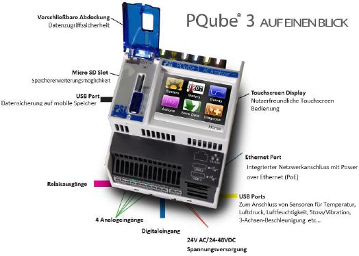
PQube 3
Das einzige Class A Messgerät, das für die neue Edition 3 des IEC Standard 61000-4-30 zertifiziert ist.
512 samples pro periode, Einsenkungen, Unterbrechungen, Spannungs und Strom Oberwellen, Flicker IEC 61000-4-15 Class F1, RVC - Rapid voltage changes, 2kHz-150kHz Emissionsschreiber, 4 MHz HF Impulse recorder, und viel mehr...
Energie (Genauigkeitsklasse 0.2/0.2s)
W, VA, VAR, λ, Wh, VAh, VARh. Berechnet kWh in jeder Minute!
Spitzenwerte über: 1 Vollwelle, 1-Minute, 15-Minuten und weitere durch den Benutzer bestimmte Intervalle
Tägliche, wöchentliche, monatliche Trends mit Lastkennlinien.
Darstellung von Verbrauchswerten - täglich, wöchentlich und monatlich.
1 A / 5 A Strommessung durch optionales CTi-5 Modul. Oder direkt nutzbar mit ultra präzisen 333 mV Strom- Sensoren. Die Wander erfüllen die Genauigkeits- anforderungen der IEC 62053-22 Klasse 0.2s und ANSI C12.20 Klasse 0.2.
NEU: PQube 3e mit 14 Stromkanäle
Viele benutzerdefinierte Kanäle und erweiterte EnviroSensoren®!
Mit zusätzlichen integrierten Wechsel- und Stromkanälen können Sie noch mehr Stromflüsse messen. Gleichzeitig benutzen Sie DC-Kanäle, um Drehzahl, Flüsse, Windgeschwindigkeit, Drehmoment, Temperatur aufzuzeichnen - was auch immer Sie sich vorstellen können! Dann stecken Sie ein paar PSL Advanced EnviroSensors® ein, um Temperatur, Feuchtigkeit, Luftdruck, Beschleunigung / Vibration und sogar Sonneneinstrahlung zu verfolgen.
- Spannungsüberwachung für Netze mit 16,7 Hz/50 Hz/60 Hz- 400 Hz, in Einphasensystemen 69 V ~ 480 V (L-N), in Dreiphasensystemen 100 V ~ 600 V (L-L) ohne Sternpunkt und 100 V ~ 830 V (L-L) mit Sternpunkt
- Geeignet für Spannungswandler
- 8 Stromeingänge, 3 Kanäle für ein Dreihphasensystem zur Leistungs- und Energiemessung
- Automatische Erkennung der Netzkonfiguration, Nennspannung und Nennfrequenz.
- 4 Analogeingänge, 1 Digitalausgang, 1 Relaiskontakt.
- Optional bis zu 2 Sensoren für Temperatur/Luftdruck/RH.
- Spannungsversorgung mit 24 VAC, 24 -48 VDC, PoE (Power over Ethernet) oder mit einem optional- einsteckbaren Netzteil für 100 -240 VAC.
- Optionales USV-Modul für ~ 30 min Backup.
- Datenspeicherung auf internem 8 GB Speicher. herausnehmbare 8 GB micro-SD Karte und USB- Schnittstelle zur Datenübertragung auf USB-Stick.
- Farb-Touchscreen Display
- Montage auf Hutschiene
Power Quality Messungen, Klasse A Ed. 3
- Power Quality Messungen, Klasse A Ed. 3
- Zertifiziert nach IEC 61000-4-30, Klasse A, Ed. 3.
- Aufzeichnungsrate mit 512-samples-per-cycle.
- Aufzeichnung von PQ-Ereignissen mit Kurvenform und Effektivwert, ausgegeben in Graphen.
- Unter- und Überspannungen, Unterbrechungen, Unter- und Überfrequenz als transiente Aufnahme.
- THDu, THDi & TDD; Spannungs- und Stromunsymmetrie; Flickerpegel (Pinst, Pst, Plt).
- Oberschwingungsstrom und Oberschwingungspegel sowie Zwischenharmonische bis zur 50. Ordnung.
- Tägliche, wöchentliche, und monatliche Trends mit Minimal-/Mittel-/Maximalwert
- Statistische Verteilungskurven, Histogramme und mehr.
- Automatische Erstellung von GIF-, CSV- und PQDIF- Dateien.
- Schnelle Spannungsänderungen (RVC).
- Darüber Hinaus:
- Aufzeichnung bei Verletzung der Kurvenform
- Erkennung und Aufzeichnung von 1 MHz Hochfrequenz- Impulsen (bis zu 4 MHz auf einem Kanal)
- Aufzeichnung von leitungsgebundenen Störgrößen im Bereich von 2 kHz bis 150 kHz.
PQube schreibt die Dateien auf eine SD-Karte
- Tabellenkalkulation: CSV Excel ®-kompatiblen Dateien, Ereignisse, Trends, Statistiken.
- Bilder: Ereignis-und Trend / Statistikgraphen - zweisprachige Bild Graphen Ausgabe direkt von PQube in typischen GIF-Format
- PQDIF: der IEEE-Standard für Power-Quality-Datendateien.
- Text-, XML-und HTML-Zusammenfassungen: perfekt für die Verknüpfung mit anderen Programmen.
MONTAGEVIELFALT
Der winzige, leistungsstarke PQube3 Netz-analyzer bietet flexible Einbau-möglichkeiten. Von der Hutschiene bis zu tragbar. Wenn Sie etwas zu messen haben, gibt es auch einen Platz zum Installieren.
Hutschienenmontage
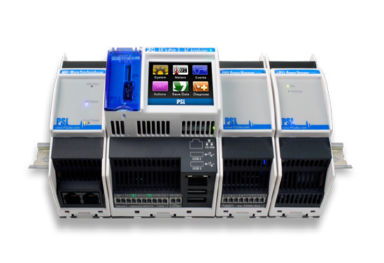
Einfach und leicht, PQube 3 können leicht auf eine bestehende Hutschiene geklippt werden.
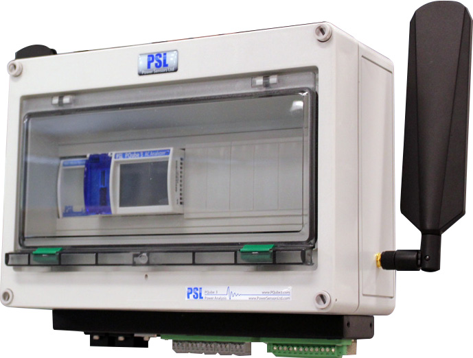
Beliebiges Gehäuse
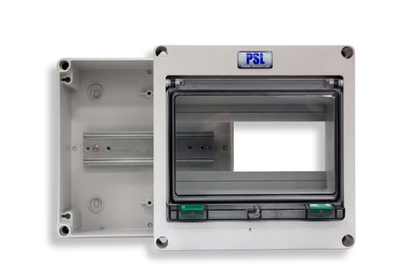
Praktisch installieren und problemlos auf Ihren PQube 3 Power Analyzer durch ein Scharnier-fenster zugreifen.
Mastmontage
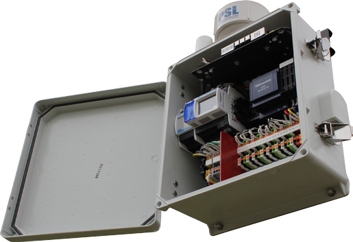
IP44-Gehäuse - ideal für die Verteilerüber-wachung. Selbstgespeist von der überwachten Spannung. 3G / 4G kompatibel.
Wandmontage
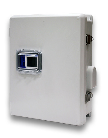
IP44-Gehäuse - ideal für robuste Innen- und Au-ßenmontage. 3G / 4G Modem kompatibel.
19" Rack-Montage
Für Rechenzentren konzipiert, kann diese einphasige Rackmontage bis zu 2 PQube 3 Analysatoren unterstützen.
Tragbar Powerside
Dieses kompakte Gehäuse ist perfekt für den Außeneinsatz geeignet. 3G/4G kompatibel.
PQube Travel
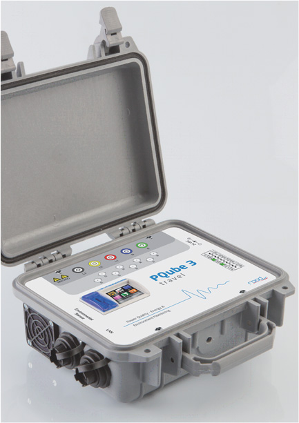
Netzqualiät-, Energie und Umweltüberwachung in einer robusten Box. Das Gerät und die Anschlüsse sind für den tragbaren Betrieb gebaut. Erweitert um UMTS Funkmodem steigert die Flexibilität.
pqube_travel_brochure_v2--_-d.pdf [532 KB]
ANSCHLIESSEN - ES IST KONFIGURIERT
Sobald Sie es montiert und verdrahtet haben, erkennt Ihr PQube 3 automatisch die Nennfrequenz-, Spannungs- und Verdrahtungskonfiguration überall in der Welt und spart Ihnen Zeit bei der Inbetriebnahme.
|
MAINS VOLTAGE MEASURING CHANNELS |
||||||||||||||
|
Mains voltage channels |
3× Line-to-Neutral, 3×
Line-to-Line, 3× Line-to-Earth, 1× Neutral-to-Earth |
|||||||||||||
|
Power configuration / |
Single-phase - 69 VAC ~ 480
VAC (L-N) Power configuration and nominal
voltages can be user-selected or auto-selected. |
|||||||||||||
|
Voltage measurement range |
0 VAC ~ 750 VAC (L-N) and 0
VAC ~ 1300 VAC (L-L) |
|||||||||||||
|
Magnitude accuracy |
|
|||||||||||||
|
Voltage fundamental angle accuracy
(relative to L1-E channel) |
|
|||||||||||||
|
Range of nominal frequencies |
16.67 Hz, Nominal 50 Hz, 60 Hz,
or 400 Hz auto-selected |
|||||||||||||
|
Simultaneous |
|
|||||||||||||
|
Frequency measurement range |
13.3 Hz ~ 23.3 Hz, 40 Hz ~ 70
Hz and 320 Hz ~ 560 Hz |
|||||||||||||
|
Input impedance |
4.8 MO || 7.33 pF to
Earth per phase |
|||||||||||||
|
Physical connection |
L1, L2, L3, N, E pluggable
screw terminal block (max torque 5 inch-pounds (0,6 Nm)) |
|||||||||||||
|
Wire connection |
Minimum wire size 20 AWG (0,52 mm2),
maximum 14 AWG (2,1 mm2) |
|||||||||||||
|
CURRENT INPUT CHANNELS |
||||||||||
|
Measurement channels |
8 inputs : I1, I2, I3, I4, I5,
I6, I7, I8 (typically used as L1, L2, L3, N, E, I6, I7, I8) |
|||||||||
|
Nominal input (Full scale) |
1A, 5A, 20A... 300A, 400A...6000A ranges
available through CTs |
|||||||||
|
Crest factor |
3.5 (±1.17 Vpk) (Low range) or
3.0 (±10 Vpk) (High range) |
|||||||||
|
Magnitude accuracy - including PSL
Ultra-Precise calibrated shielded split-core current sensors (±% rdg ±% FS) |
|
|||||||||
|
Angle accuracy - including PSL
Ultra-Precise calibrated shielded split-core current sensors |
|
|||||||||
|
Magnitude accuracy excluding
external CT's (±% rdg ±% FS) |
|
|||||||||
|
Angle accuracy - excluding external
CT's |
|
|||||||||
|
Sampling rate |
Same rate as mains voltage measuring
channels |
|||||||||
|
Input impedance/burden |
33.3 kO |
|||||||||
|
CT ratio range |
1:1 to 50000:1 |
|||||||||
|
Physical connection |
Interfaces with External CT (current
transformer) with voltage-type secondary or Flexible current sensors 5 or 8 pairs of pluggable screw terminals
(Max torque 2 inch-pounds (0,25 Nm)) |
|||||||||
|
Wire connection |
Connections to feeder wires are done by
clamping on split-core CTs around the feeder. Connection of the CT voltage output to the
PQube 3 input terminal: |
|||||||||
|
ANALOG INPUT CHANNELS |
|
|
Measurement channels |
User-selected Standard Mode or
DC Energy Mode |
|
Nominal input (Full scale) |
High range: ±60 VDC to Earth.
Low range: ±10 VDC to Earth. |
|
Measurement range |
High range: ±100 VDC, Low
range ±10 VDC. |
|
Accuracy |
±0.05% rdg ±0.05% FS typical
(1% ~ 100% FS), ANx-E |
|
Internal pull-up voltage |
2.5 VDC |
|
Analog ratio range |
1:1 to 10000:1 |
|
Input impedance |
1 MO to Earth |
|
Physical connection |
Pluggable screw terminals (Max torque 2
inch-pounds (0,25 Nm)) AN1, AN2, AN3, AN4 and Earth |
|
DIGITAL INPUT CHANNEL |
|
|
Rating |
Typical 3.3 VDC, 5 VDC, 24 VDC.
Maximum input 60 VDC (differential input) |
|
Wetting |
2.2 VDC typical. Can be used
with NC or NO dry contacts. |
|
Digital threshold |
1.5 V ±0.2V with 0.1 V
hysteresis typical. |
|
Sampling rate |
Same rate as mains voltage measuring
channels |
|
Input impedance |
>1MO |
|
Physical connection |
Pluggable screw terminals (Max torque 2
inch-pounds (0,25 Nm)) DIG1+ and DIG1- |
|
SIGNAL OUTPUT RELAY |
|
|
Connection |
RLY1
pluggable screw terminals standard |
|
Rating |
30
VAC/30 VDC, 300 mA max |
|
Function |
When
PQube 3 is off, normally open. When PQube 3 is on, normally closed. Contacts
open for duration of event or 3 seconds (whichever is longer). |
|
Operate time |
20
milliseconds |
|
POWER
MEASUREMENTS |
|
|
Definitions |
|
|
Watts (power) |
Sum
of true instantaneous per-phase bi-directional power, taken over the
measurement interval. |
|
Volt-Amps (apparent
power) |
Sum
of per-phase product of RMS voltage and RMS current, taken over the
measurement interval. |
|
Power factor |
True
power factor-ratio of |
|
VARs (volt-amps reactive) |
Fundamental
VARs on L1, L2, L3 and total |
|
Inputs |
|
|
Voltages |
L-N,
or L-Nm for delta
configurations. Nm defined
as measurement neutral, the instantaneous mean of the three L-E voltages. |
|
Currents |
L1,
L2, L3 |
|
Measurement interval |
Phase-locked,
10-cycles (50 Hz nominal) or 12-cycles (60 Hz nominal). |
|
Accuracy including PSL
|
|
|
Watts (power) |
±0.1%
rdg typical at unity power factor, nominal voltage, 10% ~ 100% FS current. ±0.2%
rdg typical at 0.5 power factor, nominal voltage, 10% ~ 100% FS current. |
|
Watt-hours (energy) |
Accuracy certified to ANSI
C12.20 Class 0.2 and IEC 62053-22 Class 0,2S |
|
CLASS A POWER QUALITY MEASUREMENTS - IEC 61000-4-30 Ed. 3 Class A, full compliance certification |
|
|
Frequency |
Range 14 Hz ~ 20Hz, 40 Hz ~ 70 Hz and 320 Hz
~ 560 Hz, Accuracy ±0.01 Hz, steady state |
|
Voltage amplitude |
Range 10% ~ 200% of nominal -
Accuracy ±0.1% Udin (Udin = 120 V, 230 V) |
|
Flicker |
Pinst, Pst,
Plt fully
compliant and certified to IEC 61000-4-15 Ed. 2 Class F1 |
|
Voltage
dips/swells/interruptions |
Fully compliant and certified
to IEC 61000-4-30 Ed. 3 Class A, Accuracy ±0.2% of nominal voltage, duration
accuracy : ±½ cycle at beginning of event and ±½ cycle at end of event,
hysteresis selectable |
|
Rapid voltage changes (rvc) |
Fully compliant and certified
to IEC 61000-4-30 Ed. 3 Class A - Accuracy 0.2% |
|
Unbalance |
Fully compliant and certified
to IEC 61000-4-30 Ed. 3 Class A |
|
Voltage harmonics and interharmonics |
Fully compliant and certified
to IEC 61000-4-30 Ed. 3 Class A |
|
Mains signaling voltage |
Fully compliant and certified
to IEC 61000-4-30 Ed. 3 Class A |
|
Underdeviation and overdeviation |
Fully compliant and certified
to IEC 61000-4-30 Ed. 3 Class A |
|
BEYOND CLASS A - 2 kHz-150 kHz CONDUCTED EMISSIONS MEASUREMENT |
|
|
Measurement method |
Fully compliant and certified to IEC 61000-4-30 Ed. 3, Annex C
(informative) |
|
Range |
0-60 Vpk |
|
BEYOND CLASS A - HIGH FREQUENCY IMPULSE |
|
|
Sampling rate |
4 MHz on single channel, the
channel is user selected. |
|
Accuracy |
±5% typical. Dependent on frequency and type of impulse |
|
Range |
±6 kVpk.
User-selectable threshold through 2-pole 1.5 kHz high-pass filter, and 1.5
MHz low pass filter |
|
Measurement |
Fully compatible with
ANSI/IEEE C62.41, C3 and B3 combination wave, ring wave and IEC 61000-4-5
waveforms |
|
ENVIROSENSOR PROBES (TEMPERATURE/HUMIDITY/PRESSURE/ACCELERATION) |
|
|
Connection |
USB. Functional electrical
isolation from PQube 3 |
|
Sampling rates |
1 sample per second typical
for temperature, humidity, barometric pressure 8, 16, 32 samples per second,
user selected for acceleration |
|
Temperature |
Range: -20 °C ~ +80 °C (-4 °F
~ 176 °F) |
|
Humidity |
Range: 0 %RH ~ 100 %RH (useful range: 20 %RH ~ 80 %RH)
|
|
Barometric pressure |
Indicative measurements,
resolution better than 0.001 hPa |
|
Acceleration |
Full-scale acceleration ±2g,
±4g, ±8g, user selected Trigger on mechanical
shock/vibration, seismic motion, or tilt |
|
OPTIONAL ATT1 VOLTAGE ATTENUATOR MODULES FOR ANALOG
INPUT CHANNELS |
||
|
|
ATT1-0600V |
ATT1-1200V |
|
Rated full-scale voltage |
±600 VDC/300 VAC to Earth |
±1200
VDC/600 VAC to Earth |
|
Nominal
measurement range |
±825 Vpk to Earth |
±1630
Vpk to Earth |
|
Test voltage to earth |
7250 VDC |
14500
VDC |
|
Accuracy |
±0.2% reading typical at DC (>10% FS), plus uncertainty
of PQube 3 analog input channels |
|
|
OPTIONAL
ATT2 MODULE FOR DC POWER AND ENERGY |
|||
|
Voltage
channel |
ATT2-600V |
ATT2-1200V |
|
|
Maximum input voltage |
±1000
Vpk differential |
±2000
Vpk differential |
|
|
Rated full-scale voltage |
±600
VDC/300 VAC differential |
±1200
VDC/600 VAC differential |
|
|
Analog input ratio |
100:1 |
200:1 |
|
|
Accuracy |
DC:
±0.1% rdg ±0.1% FS 50/60Hz:
±0.15% rdg ±0.15% FS typical (At
23°C ±3°C, 10% - 100% FS, not including uncertainty of PQube 3 analog
channels) |
||
|
Thermal drift of offset voltage |
±0.005
mV/°C typical |
|
|
|
Thermal drift of gain |
±0.01%
rdg/°C typical |
|
|
|
Current channel |
With closed-loop sensors |
With open-loop sensors |
|
|
Rated full-scale current |
50A
to 600A (depending on sensor model) |
50A
to 3000A (depending on sensor model) |
|
|
Maximum input current |
150%
to 200% FS (depending on sensor model) |
110%
to 200% FS (depending on sensor model) |
|
|
Accuracy
at calibration current |
±0.15%
rdg ±0.15% FS typical at DC |
±0.3%
rdg ±0.3% FS typical at DC |
|
|
|
At 23°C ±3°C. Calibration
current = 70% FS or 500A (whichever is smaller). Does not include uncertainty of PQube 3 analog
channels |
||
|
Hysteresis offset voltage error |
<
±20 mV (after excursion of ±100% FS current) |
<
±30 mV (after excursion of ±100% FS current) |
|
|
Linearity (from 10% to 100% FS) |
±0.1%
rdg ±0.1% FS |
±0.5%
rdg ±0.5% FS |
|
|
Thermal drift of offset voltage |
±0.1
mV/ºC typical |
±1
mV/ºC typical |
|
|
Thermal drift of gain |
±0.02%
rdg/ºC typical |
±0.1%
rdg/ºC typical |
|
|
INSTRUMENT
POWER SUPPLY |
|
|
PQube 3 power supply screw
terminals - supports AC or DC |
PQube 3 P+ and P- pluggable
screw terminals |
|
AC
input range |
24 VAC ±10% at 50/60/400 Hz, 1.5A max |
|
DC
input range |
±24 VDC ~ 48 VDC ±10%
(polarity independent), 1A max |
|
Power consumption |
20W max |
|
Isolation |
Internally electrically
isolated from all other circuits to avoid ground loops. |
|
PQube 3 - PoE - Power over
Ethernet (standard) |
|
|
Input voltage range |
37 ~ 57 VDC |
|
Power
consumption |
15W max |
|
PM1, PM2 Power Manager Modules (optional) |
|
|
Rated
AC input range |
100 ~ 240 VAC ±10%, 50/60 Hz |
|
AC
input current rating |
400 mA |
|
Supported
DC input range |
120 ~ 370 VDC |
|
Auxiliary
DC power output |
24 VDC isolated, up to 5.15W
max (Available with PM2 only) |
|
Power
consumption |
20W max |
|
Isolation |
|
|
Surge
immunity |
EN 61000-4-5 Criteria A |
|
Installation
category |
CAT II 300V |
|
UPS1 BATTERY BACKUP MODULE |
|
|
PQube 3 backup time |
1 ~ 30 minutes, user selected. |
|
Battery |
7.4 V 2200mAh Li-ion battery
pack |
|
Life expectancy |
3 years or 500 cycles (100% depth discharges), whichever comes
first. |
|
Operating temperature range |
0 °C ~ 45 °C |
|
Operating humidity |
45 %RH ~ 85 %RH |
|
Protection |
Built-in hardware cutoff for over-voltage,
under-voltage, and overcurrent. |
|
UPS2 BATTERY BACKUP MODULE |
|
|
PQube 3 backup time |
1 ~ 60 minutes, user selected. |
|
Battery |
6.0 V , with one or several 2500mAh
lead-acid external battery packs |
|
Life expectancy |
10 years or 300 cycles
(100% depth discharges), whichever comes first. |
|
Operating temperature range |
-20 °C ~ 65 °C |
|
Operating humidity |
45 %RH ~ 85 %RH |
|
Protection |
Built-in hardware cutoff for over-voltage,
under-voltage, and over-current. |
|
STORAGE/COMMUNICATIONS |
|
|
USB |
|
|
Connection |
Three USB master ports: one
hi-speed USB2.0 port, two standard USB1.0 ports |
|
Isolation |
PQube 3 provides functional
isolation to Earth (eliminates ground loops). |
|
Removable SD card |
|
|
Type |
microSD |
|
Capacity |
16GB standard (stores up to 3
years of data under normal use) |
|
Ethernet Port |
|
|
Connection |
Standard RJ-45 socket (wired
Ethernet). Transformer isolated. |
|
Email |
Sends emails after every event
with data attached; user request real-time meters via e-mail, PQube 3
firmware upgrade via email, change PQube 3 setup via email, incoming e-mail
filters. Includes GIF graphs, CSV spreadsheet files, PQDIF, HTML and XML
summaries |
|
Web server |
More than 30 real-time meters.
All events, trends and statistics recordings. Includes GIF graphs, CSV
spreadsheet files, PQDIF, HTML and XML summaries. |
|
Modbus
over TCP |
More than 50 real-time meters
with update rate of approximately 0.5 seconds - see PQube 3 Modbus
Specification document. Event/trend-statistics counters can be used for
triggering downloads via FTP or web server. |
|
FTP
Server |
File Transfer Protocol.
Transfers files from PQube 3 SD card to and from any computer. |
|
SNTP |
Simple Network Time Protocol
for synchronizing PQube 3 real-time clock to UTC. |
|
SNMP |
Support for SNMP v2c and v3 |
|
Security
|
Secure FTP- FTPS, HTTPS. |
|
CLOCK TIMING |
|
|
Internal real-time clock |
Fully compliant with IEC 61000-4-30 Ed. 3
Class A |
|
SNTP |
Accuracy: ±10 to 100 milliseconds
absolute, UTC time. Dependent on network latency. |
|
NTP |
Accuracy: ±1 to 10milliseconds absolute,
UTC time. Dependent on network latency |
|
GPS (with optional MS1 module and GPS
receiver) |
Intrinsic
resolution 1microsecond |
|
OPERATING ENVIRONMENT |
|
|
Operating temperature |
Minimum -20 °C, Maximum 65 °C with no load
on 24V power supply terminals, Maximum 55°C with 5.15W load on 24V power
supply terminals |
|
Operating humidity |
5% RH ~ 95% RH non-condensing, indoor use |
|
Altitude |
Maximum 2000 meters above sea level |
|
Overvoltage category |
For PQube 3 AC mains measuring terminals,
Overvoltage Category III 600V. |
|
Pollution degree |
2 |
|
Isolation |
UL/IEC 61010:2010 - 3.6 kV AC
1 min, 5.1 kVDC 1 min, 5.4 kVAC (5 sec), 9.6 kVpk impulse. |
|
Surge |
UL/IEC 61010:2010 - 3.6 kV AC
1 min, 5.1 kVDC 1 min, 5.4 kVAC (5 sec), 9.6 kVpk impulse. |
|
Installation category |
CAT IV UL/IEC 61010 for
voltages up to 300 VAC L-N (equivalent to 480 VAC L-L), CAT III for voltages
up to 600 VAC L-N. Pollution degree 2. |
|
Transient voltages |
100 kHz ring wave, 6 kVpk, IEC
61180, IEC 61000-4-5. Applied to voltage measuring terminals with Performance
Evaluation Class 1. (When applied to optional power supply mains terminal,
supply's fuse may operate in PE Class 3 at test levels greater than 4 kV.) |
|
EFT burst immunity |
4 kVpk, IEC 61000-4-4,
Performance Evaluation Class 1. Applied to power measuring terminals and
optional PM1/PM2 power supply mains terminals. |
|
RF field strength immunity |
3 V/m, IEC 61000-4-3 Test Level 2. |
|
Magnetic field strength immunity |
30 A/m, IEC 61000-4-8 Test Level 4. |
|
Ingress protection rating (IP rating) |
IP20H, IEC 60529. |


Dokumente
- pqube3-de.pdf [3.018 KB]
- pqube-3-brochure-rev-3.0-d.pdf [2.410 KB]
- pqube-3e-brochure-v5-_-d.pdf [600 KB]